
Requirements
The RC Baja Car Suspension required all of the following:
-
Suspension must support up to 6 pounds upon a 2 foot drop without aid of a chassis
-
Shock absorption system must be designed to damped the force of a 2 foot drop for a 6 pound car
-
Suspension must have at least 1 inch of travel
-
Steering system must articulate fully without interfering with any other parts
-
Body of car must fit within the diameter of the wheels so that it may be driven if flipped upside down
-
Steering must allow for a 5 foot turn diameter
-
System must be fastened together with easily sourced fasteners
Analysis
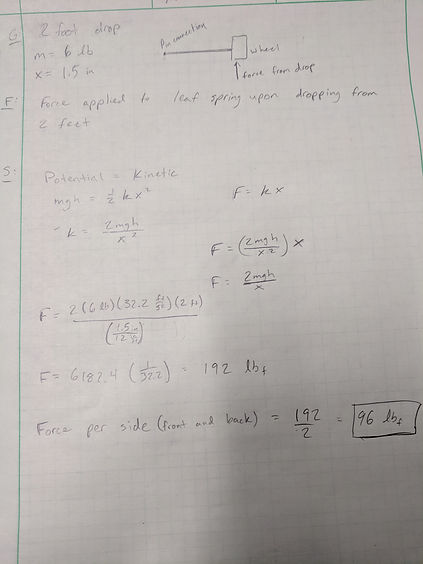
Analysis started with determining how much force would be applied to a single side if the RC car were to fall from a worst-scenario 2 feet. The car has an estimated maximum weight of 6 pounds. Using this data, a force was determined using energy equations and force equations using spring constants. This force will be applied to the leaf spring suspension, so using energy and force equations with spring constants was applicable. With a given maximum deflection of 1.5 inches, the force from a two foot drop was 192 pounds force. Since there are two sides (front and back) to the leaf spring suspension, each side will have a 96 pounds force impact after the two foot drop.
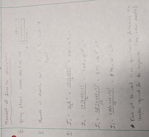
With this information, the length of the leaf spring suspension could be calculated. The leaf spring will consist of three layers of spring steel at 0.025 inches thick per layer and 1 inch wide. The spring's length was determined using cantilever beam deflection. The maximum deflection was the same as before at 1.5 inches. As a result, the length of the spring from the pinned point at the center to the wheel where the forces were applied is 3.66 inches. This equates to an overall length of 7.32 inches, and the team decided to round to an even 7.5 inches for added simplicity.
After finding appropriate material in the machine shops on CWU’s campus, the leaf spring layers were to be made with spring steel that was 0.039 inches thick instead of the suspected 0.025 inches. This adjusted how many layers would be needed. After some tinkering with the calculations that were made in the same analysis as above, the team could finalize the design with two layers of spring steel rather than three.
A suitable fastener had to be selected for the attaching the leaf spring to the chassis. The set screw had to be made of stainless steel and have a diameter wide enough to withstand the force from a 2-foot drop as determined above. Using the allowable stress determined with a safety factor of 2, dividing the load by the cross sectional area was the equation used. The diameter of the screw could be solved with this equation, and it was determined to be 0.087 inches. This represents the minimum diameter needed to achieve a safety factor of two, so the team decided on #6 machine screws, which meet the minimum requirement.
In the proposal for the drivetrain, it is stated that the car is required to achieve a top speed of 20 miles per hour. Given this, a maximum impact force could be calculated for a 6 pound vehicle hitting a wall and coming to a stop. Using the equation for force being equal to the mass multiplied by the change in velocity, a maximum force of 586 pounds force per wheel was determined (see Figure 7 in Appendix A).
The upper mounts had to be able to withstand any forces that the wheels have to go through. The team decided to make them out of ABS plastic with a rapid prototyping machine. As a result, the mounts are not as strong as they could be if made from a stronger material. Early spring quarter will likely consist of machining new mounts that can withstand the same forces as the leaf spring layers.
Calculations
Wheel deflection after 2-foot drop

Leaf spring length
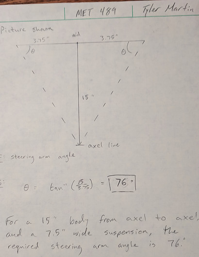

Steering arm angle
Minimum screw diameter


Deflection at leaf spring housing
Impact force
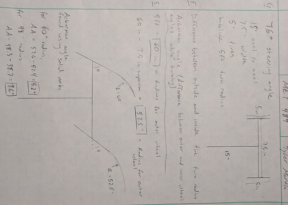
Ackermann Angle
Moment of Inertia