CONSTRUCTION

The project was designed and analyzed on the CWU campus. While working within the constraints of the University’s resources, the frame of the vehicle will be created using two different materials: three-dimensional printing plastic and aluminum. The steering components and wheel hubs will be made using SolidWorks and the available rapid prototyping machine, while the chassis and suspension will be made by shaping thin aluminum and steel materials.
The first step in construction will be designing the chassis to be long enough to keep the drive train belt taut. The other member of the team designed for a 15-inch belt, so the chassis was cut to 17 inches for some extra room at each end. In order to hold the motor safely on the chassis without it hanging off the edge, it was cut to be seven inches wide. Finally, 2x2 inch sections in the middle of each end were cut for locating the differential mounts and the leaf spring suspension. Below is an image of the chassis.
The next step will be constructing the suspension. A housing of 6061 Aluminum was machined using the facilities on campus at CWU. The housing is 1 inch wide by 2 inches long, and is a half-inch thick. Four holes were drilled into the material down the middle for use in mounting the leaf springs as well as mounting the housing to the chassis. The most difficult aspect of these parts was machining the thin, 1/8th inch thick slot in the middle for the leaf springs to fit through. Achieving this required the use of a 1/8th inch end mill, which will break at the slightest misstep. After meticulous machining at a mill, the slots turned out just fine, and were the perfect width to fit the entirety of the leaf spring system. An image of the leaf spring housing can be seen below.
After making the housings, cutting the leaf spring layers was the next step. Cutting the spring steel to length was done using resources within Hogue Hall on campus grounds. Once the measuring and scratching sections in the sheet of steel was finished, a manual shear easily cut the thin layers. The sharp corners were rounded off and holes were drilled for the set screws. Each layer of the leaf spring system will be pinned together using 10-32 set screws, which were acquired from the resources on campus. The next image shows one of the leaf spring suspensions in its completed form, ready for mounting to the chassis.
With the suspension out of the way and ready for assembly, using the rapid prototype machine was the next step. Unlike RC cars made in previous which used store-bought steering mechanisms, the team decided to try and design a steering system that could fit in-between the drive train belt. Since there was only around 1 inch of clearance between the taut and slack belt sides, the steering took on a slim and efficient design. It consists of a mount with two circular posts. Each post will hold a rotating arm which will be connected using steering linkages and spring steel. The posts have a hole in the top where a pin will be press fit in order to keep the arms from falling off. Even if the team decides to remove the belt from the car entirely, the steering system will still be perfectly fine to use. Below is an image of the steering mount and arms, which are attached to the steering servo using a steering linkage.
The final task for this team member’s half of the construction was to design the wheel carriers. The original thought for the design was to use a square-style steering knuckle that could easily maneuver the wheels. However, having 4-wheel drive in mind changed everything. The team was able to find viable wheel carriers with a mount for the steering linkages. They were not at the specified angle that was determined in the analysis, but the steering linkages can move freely to fit to the required angle. Mounts for the wheel carriers to attach to both the leaf spring suspension and the upper mounts were machined out of aluminum. The system in its entirety can be seen in the image below.
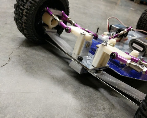
In spring quarter several things about the vehicle changed. The biggest change was switching from 4 wheel drive to 2 wheel drive. As a result, the belt was removed from the vehicle. This change occurred because the drive shafts that were back ordered came in and were too short for the width of the suspension. If the front wheels were going to be able to turn safely, there was no way that the drive shafts could have fit in the front. The rear suspension was cut down to a narrower width to fit the drive shafts, which can be seen in the image below. The last piece added was a spine along the bottom to support the thin chassis material, which was deforming under the weight of the various electronics attached to the car. The final image shows the completed car, with the shortened rear suspension and all the electronics in place.